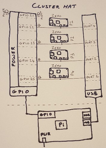
The Cluster HAT basically comprises of a USB 2.0 hub and independent I2C or GPIO controlled power for each Pi Zero (and Alert LED).
USB Hub
When looking at the USB ports used for the Pi Zeros in "lsusb -t" you will see they're not connected USB Port 1->P1, they are connected as follows. Knowing this can be useful when checking you have the correct image on the SD card for example.
- USB Port 4 -> Pi Zero P1
- USB Port 3 -> Pi Zero P2
- USB Port 2 -> Pi Zero P3
- USB Port 1 -> Pi Zero P4
The Cluster HAT v2.x uses an 8-bit I2C I/O Expander (Exar XRA1200P / TI PCA9554)
- Port/bit 0 - Power Pi Zero P1
- Port/bit 1 - Power Pi Zero P2
- Port/bit 2 - Power Pi Zero P3
- Port/bit 3 - Power Pi Zero P4
- Port/bit 4 - Enable / Disable LED Power
- Port/bit 5 - Enable / Disable USB Hub
- Port/bit 6 - ALERT LED
- Port/bit 7 - EEPROM Write Protect
Power Control
- GPIO21 - ALERT LED
- GPIO22 - Power Pi Zero P1
- GPIO23 - Power Pi Zero P2
- GPIO24 - Power Pi Zero P3
- GPIO25 - Power Pi Zero P4
N.B. GPIO pins 22-25 DO NOT power the Pi Zero directly they are only used for control.
From the Controller Pi power to the Pi Zeros can be controlled using the "clusterctrl <action> <devices>" command on our configured images.
Cluster HAT v2.x Cluster HAT v1.x
$ clusterctrl on # Turn power to all Pi Zero on
$ clusterctrl off  Turn power to all Pi Zero off
$ clusterctrl on p1 # Turn power on to Pi Zero in slot P1
$ clusterctrl on p1 p3 p4 # Turn power to Pi Zeros in slot P1, P3 and P4 on
$ clusterctrl off p2 p3 # Turn power off to Pi Zeros in slots P2 and P3
$ clusterctrl alert on # Turns on ALERT LED
$ clusterctrl alert off # Turns off ALERT LED
Cluster HAT v2.x (commands not available on Cluster HAT v1.x)
$ clusterctrl hub on # Turns on USB hub (default)
$ clusterctrl hub off # Turns off USB hub
$ clusterctrl led on # Enables Power & P1-P4 LED on Cluster HAT (default)
$ clusterctrl led off # Disables Power & P1-P4 LED on Cluster HAT (does not disable ALERT LED)
$ clusterctrl wp on # Write protects HAT EEPROM
$ clusterctrl wp off # Disables EEPROM write protect (only needed for updates)
Custom Control
If you're not using our images you can download our clusterctrl script (may need modification for your configuration) or use i2cset/gpio(wiringpi tool) to directly toggle the I/O expander or GPIO pins.
I2C Control
In the command line examples below we're using the i2cset tool. You can use other commands/languages to communicate with the I2C expander such as C, C++, Python, etc. To follow the examples install the command line tool.
apt-get install i2c-tools
As the Cluster HAT is controlled by I2C you must first ensure I2C is enabled in the kernel. On Raspbian based distributions this can be enabled using raspi-config.
Depending on availability we currently use XRA1200P and PCA9554 I/O expanders (datasheets linked above), the registers 0, 1, 2 and 3 work in the same way for both of these devices.
Controlling the Cluster HAT using the I/O expander is a little more complicated vs the GPIO interface used by the Cluster HAT v1.x but allowed many new features to be added. Here we're only showing the basics of initial initialisation, turning on/off Pi Zeros, HUB and ALERT LED.
To initialize the I/O expander the "direction" register needs to be set but care is needed in case the POS (power on state) jumper has been cut (to automatically power on the Pi Zeros). If you don't need to check this you can jump to the "Set all pins on the I/O expander to outputs" section below.
First check if the direction register is still set to it's default value 0xff (has the I/O expander been initialised).
# Get I/O expander direction register
i2cget -y 1 0x20 3
If the value is not 0xff then the expander has been initialised so skip directly to controlling power to the Pi Zeros below.
If the direction regiser is 0xff you will need to read the logic levels on the I/O expander pins to detect POS.
i2cget -y 1 0x20 1If the low nibble of this value is an 'F' (0x?F) it means all Pi Zeros are powered on and the POR jumper has been cut so all Pi Zeros need to be powered on before setting the expander pins to outputs.
# POR has been cut so turn on P1-P4
i2cset -y -m $((2#000001111)) 1 0x20 1 0xff
# Turn off the ALERT LED
i2cset -y -m $((2#01000000)) 1 0x20 1 0x00
Set all I/O ports to be outputs.
# Set all pins on the I/O expander to outputs
i2cset 1 0x20 3 0x00
Then ensure the USB hub is powered on. For a Version 2.0 the HUB bit (5) needs to be set to 1, for versions >2.0 the bit needs to be set to 0.
# Version 2.0 turn HUB on (set bit 5 to 1)
i2cset -y -m $((2#00100000)) 1 0x20 1 0xff
# Version >2.0 turn HUB on (set bit 5 to 0)
i2cset -y -m $((2#00100000)) 1 0x20 1 0x00
# Version 2.0 turn HUB off (set bit 5 to 0)
i2cset -y -m $((2#00100000)) 1 0x20 1 0x00
# Version >2.0 turn HUB off (set bit 5 to 1)
i2cset -y -m $((2#00100000)) 1 0x20 1 0xff
The above i2cset command options can be broken down as.
- "-y" - To disable interractive mode
- "-m $((2#00100000))" - is the mask of which bit(s) to set (here we're using bash to convert from binary to decimal. If you know the decimal or hex you can set this directly as "-m 64" or "-m 0x40" for example).
- "1" - is the I2C bus we're communicating on.
- "0x20" - is the address of the I/O expander.
- "1" is the Register we're reading/writing to [0=Input register(all pins are outputs by default which is what we need), 1=Output Control (set bit to 1 to set pin high). Details of the other regisers can be found in the datasheets for each I/O expander.]
- Then we use either "0x00" (to set the bit(s) set to 1 in the mask to 0) or "0xff" (to set the bit(s) set to 1 in the mask to a 1).
We use the mask option (-m) to i2cset which first initiates a read of the specified register, this value is then masked and written back to the register it was read from. With the above commands this enables you to toggle single bits on the I/O expander without having to manually read the value first and calculate the value needed to toggle a single bit.
Once the USB hub is powered on you can control the Pi Zeros.
# Turn Pi Zero P1 on (set bit 0 to 1)
i2cset -y -m $((2#00000001)) 1 0x20 1 0xff
# Turn Pi Zero P1 off (set bit 0 to 0)
i2cset -y -m $((2#00000001)) 1 0x20 1 0x00
# Turn Pi Zero P2 on (set bit 1 to 1)
i2cset -y -m $((2#00000010)) 1 0x20 1 0xff
# Turn Pi Zero P2 off (set bit 1 to 0)
i2cset -y -m $((2#00000010)) 1 0x20 1 0x00
# Turn Pi Zero P3 on (set bit 2 to 1)
i2cset -y -m $((2#00000100)) 1 0x20 1 0xff
# Turn Pi Zero P3 off (set bit 3 to 0)
i2cset -y -m $((2#00000100)) 1 0x20 1 0x00
# Turn Pi Zero P4 on (set bit 4 to 1)
i2cset -y -m $((2#00001000)) 1 0x20 1 0xff
# Turn Pi Zero P4 off (set bit 4 to 0)
i2cset -y -m $((2#00001000)) 1 0x20 1 0x00
Similary the ALERT LED can be controlled by setting bit 6 high(on)/low(off).
# Turn ALERT LED on (set bit 6 to 1)
i2cset -y -m $((2#01000000) 1 0x20 1 0xff
# Turn ALERT LED off (set bit 6 to 0)
i2cset -y -m $((2#01000000)) 1 0x20 1 0x00
For full details please see our standard clusterctrl script which detects the pullups on P1/P4 to detect initial power on state, turns all LED on/off, etc.
GPIO Control
The WiringPi tool is normally installed on the Cluster HAT images but if you're using another distribution you may need to install it to use the examples below.
apt-get install wiringpi
The Controller GPIO pins are automatically configured by the Cluster HAT to be outputs so the Pi Zero power can be enabled/disabled using simple commands.
# Turn on ALERT LED
gpio write 21 1
# Turn off the ALERT LED
gpio write 21 0

# Turn on Power for Raspberry Pi Zero P1
gpio write 22 1
# Turn off power for P1
gpio write 22 0

# Turn on Power for Raspberry Pi Zero P2
gpio write 23 1
# Turn off power for P3
gpio write 23 0

# Turn on Power for Raspberry Pi Zero P3
gpio write 24 1
# Turn off power for P3
gpio write 24 0

# Turn on Power for Raspberry Pi Zero P4
gpio write 25 1
# Turn off power for P4
gpio write 25 0
The above commands can be used in scripts to turn on/off and cycle the power to each Pi Zero individually. We advise staggering the power up of the Pi Zero by a couple of seconds to stage the increase in power requirement on your power supply.